Erosion-Corrosion (Impingement) Attack
Approximately 80% of all tube failures occur within the first couple inches of the heat exchanger tube inlet-end. This is referred to as inlet-end erosion. The solution to this problem is the use of a thin wall, metal tube insert expanded full length into the inlet-end of condensers and heat exchangers. Ideally, tube inserts are installed in units when originally manufactured. However, if they were not, tube inserts can compensate for any existing damage and protect the inlet from further damage. The tube insert is designed to ensure a smooth and gentle transition of the fluid down the tube insert to the condenser or heat exchanger tube. The tube insert is sacrificial and designed to absorb the tube damage that would normally occur to the condenser or heat exchanger tube. It is far less expensive to replace a 6 inch tube insert than a 20 or 40 or 60 foot condenser. or heat exchanger tube. The US Navy uses tube inserts in its surface vessels. To quote advisory number 003-82, “Installation of inserts is recommended for all surface vessels to extend the service life of A/C condenser tubes, and will be immediate value to those classes with known erosion/corrosion problems.” Also reported were the results of a Navsses conducted fleet techeval, which confirmed that the tube inserts afforded excellent protection against erosion/corrosion, even when installed in tubes which already had advanced pitting. Figures 1, 2 and 3 are typical designs of a tube insert for this application.
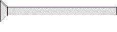
Figure 1
![]()
Figure 2
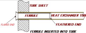
At NSI, we recommend the use of the tube insert in Figure 3. The feathered ends provide a smooth transition of the fluid from the insert to the parent tube. However, this design is more costly than Figure 1. Figure 1 should only be considered when the unit is going to be retired within a couple of years. Figure 1 has a tendency to transfer the erosion problem to the end of the tube insert. Figure 4 represents how a tube insert with a flared end and feathered end is positioned within a unit. The end of the parent tube is not completely protected. In Figure 5 with the use of a flanged end and feathered end, the parent tube is completely protected on the inlet-end and the outlet-end of the ferrule provides a smooth transition. The angle on the outlet-end should not be in excess of 15 degrees.